| Search for content and authors |
Numerical study of argon gas flow in a semi-industrial crystallization furnace for the production of multicrystalline silicon ingots |
| Martin P. Bellmann 1, Dag Lindholm 2, Dag Mortensen 2, Mohammed M'Hamdi 3 |
|
1. SINTEF Materials and Chemistry, Trondheim 7028, Norway |
| Abstract |
In directionally solidified multi-crystalline silicon, oxygen and carbon are the impurities that present by far the highest level. Oxygen from the silica crucible dissolves into the melt, incorporates into the crystal or forms silicon monoxide which evaporates from the free melt surface. Argon inert gas, injected into the furnace chamber, carries the silicon monoxide to the hot graphite fixtures where it reacts with carbon to form carbon monoxide and silicon carbide. Carbon monoxide is carried by the inert gas to the melt free surface, where it dissociates into carbon and oxygen. Finally, oxygen and carbon are incorporated into the crystal. Oxygen related defects, like thermal and new donors, can reduce the minority carrier lifetime in solar cells. Carbon precipitates can be responsible for the nucleation of new grains, the formation of locally induced stresses, wire-sawing defects and can cause ohmic shunts in solar cells. The final impurity distribution in the solidified ingot strongly depends on the melt [1] and gas flow [2] velocity fields. Tailoring the melt flow, e.g. by external force fields [3], and the gas flow field, provides tools for controlling the impurity distribution in the ingot and gas phase. A global model of a semi-industrial crystallization furnace including heat transfer by conduction, convection and radiation is used to study the argon gas flow field. The induction heated furnace holds 120 kg of silicon, producing squared ingots of 55x55 cm and 16.5 cm in height. A special feature of the furnace is the argon gas injector, which consists of two nozzles allowing to control the flow in horizontal and vertical direction independently. In the paper the impact of different flow rate combinations (horizontal/vertical) on the gas flow pattern are studied and discussed with respect to impurity transport. The furnace model and the mesh are shown on the left hand side in Fig. 1 and the calculated argon gas flow field on the right hand side. 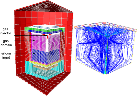
Fig. 1: Global furnace geometry with mesh and furnace parts and simulated argon gas flow field (pathlines). [1] M.P. Bellmann et al., Journal of Crystal Growth 362 2013, 93. [2] M.P. Bellmann et al., Journal of Crystal Growth 369 2013, 47. [3] P. Rudolph, K. Kakimoto, MRS Bulletin 34, 251. |
| Legal notice |
|
Presentation: Oral at 17th International Conference on Crystal Growth and Epitaxy - ICCGE-17, General Session 4, by Martin P. BellmannSee On-line Journal of 17th International Conference on Crystal Growth and Epitaxy - ICCGE-17 Submitted: 2013-03-22 10:12 Revised: 2013-03-27 19:18 |