| Search for content and authors |
Evaluation of macro and micro-strain in the surface modification layer peened by cavitation shotless peening |
| Nao Yamada 1, Arnt A. Kern 2, Lutz Bruegemann 2, Hitoshi Soyama 3 |
|
1. BRUKER AXS K.K, 3-9-A, Moriya-cho, Kanagawa-ku, Yokohama-shi, Kanagawa 221-0022, Japan |
| Abstract |
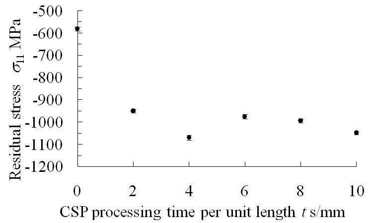
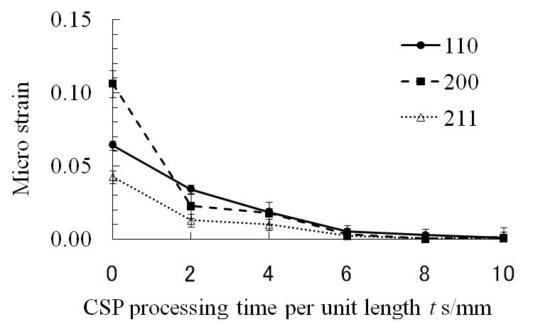
Abstract. In order to verify the detail of macro and micro-strain in the surface modification layer peened by cavitation shotless peening (CSP), macro and micro-strain is investigated using X-ray diffraction method, as macro-strain is evaluated by residual stress and micro-stain is evaluated by profile fitting approach. Surface modification is effective solution for improving strength on material surface, and there were three kinds of method, which are shot peening (SP), laser peening (LP), and CSP. CSP is using cavitation impact, and is not required shot in the process. In order to establish optimised surface modification, accurate evaluation for macro and micro-strain are required. In previous researches, compressive residual stress is introduced as macro-strain and full width of half maximum (FWHM) of peak profile is wide before SP. However, it was found that compressive residual stress is introduced as macro-strain, even though FWHM of peak profile is sharp before peening in the case of CSP. As the results of analysing peak profile using fundamental parameter (FP), it was observed that micro-strain is released in surface modification layer by CSP. 1. IntroductionPeening method for metal surface making use of cavitation impacts is called “cavitation shotless peening (CSP)”1-4, as shot in the process is not required. It was proven that CSP improved fatigue strength and life time for forging die5 and gears3 using various metals1-4. There have been some interest reports that CSP is possible to improve fatigue strength with compressive residual stress less than SP2, and compressive residual stress is observed, even though FWHM of peak profile is decreased before peening. FWHM of peak profile in XRD measurement depends on X-ray geometry, crystallite size, and crystallite strain (micro-strain). Thus, in the case of CSP, there is possibility that micro-strain is released with introducing compressive residual stress as macro-strain at the same time. However, macro-strain in the surface modification layer has been evaluated by conventional method as sin2ψ method, and micro-strain has been evaluated as FWHM value of peak profile so far. In the present paper, it was found that the transition of macro and micro-stress is evaluated with the processing time of CSP, as macro-strain is approached by 2D method7 using triaxial stress model, and micro-stress is evaluated by fundamental parameter (FP) 8-9. 2. ExperimentsCSP instrument which can generate a cavitation jet in air6 was used in this testing. The tested material was tool steel alloy Japan Industrial Standard (JIS SKD61). The size of specimen was 45 mm in length, 15 mm in width, and 18 mm in thickness. The processing time per unit length t was defined from the scanning speed ν and number of scans n as equation (1). t=n/ν (1) Micro-strain of the specimen was calculated from peak profile using FP. The XRD data for micro-strain were collected by θ–θ diffractometer and Bragg Brentano geometry equipped with Cu tube operated at 40 kV, 40mA and Cu Kα radiation was used. The step size of scan was set as 0.02 degrees and the exposure time was set as 20 seconds per step. Divergence slit and anti-scattering slit were set as 0.5 degrees, receiving slit was set as 0.1 mm, and axial soller slit was set at incident side and receiving side as 2.5 degrees. Detector was chosen as solid state detector. α-Fe (110), (200), and (211) were collected for micro-strain analysis. The data for macro-strain were collected by horizontal diffractometer using two-dimensional (2D) detector equipped with Cr tube operated at 35 kV, 40mA and flat graphite monochromator was used at incident side and Cr Kα radiation was used. X-ray beam was collimated as 0.8 mmφ. α-Fe (200) (2θ =106 degrees) was collected for residual stress measurement. Exposure time was set as 10 minutes per frame and 21 frames were collected with changing φ and ψ axis. The residual stress of normal stress σ11, σ22, σ33 and shear stress σ12, σ13, σ23, were calculated from 21 frames by using 2D method. Young’s modules and Poison’s ratio were used 210 GPa and 0.28. 3. Results and ConclusionsThe σ11 direction of residual stress on the surface as a function of processing time per unit length is shown figure 1. The compressive residual stress was increased approximately -600 MPa to -1000 MPa with increase of the processing time by CSP. The compressive residual stress is saturated and almost stable with an increase the processing time t ≥4 s/mm. However, the compressive residual stress was obviously increased with an increase the processing time t ≤ 2 s/mm. This means that the compressive residual stress is certainly increased as macro-strain by CSP. Figure 2 shows that the micro-strain, which was evaluated using FP at α-Fe 110, 200, and 211 reflections. The micro-strain was decreased with increase of the processing time by CSP at all reflections In the present paper, it was proven that the micro-strain, which might be introduced by the heat treatment and mechanical finishing, was released less than 1/10 by CSP, even though CSP introduced the compressive residual stress. Additionally, it was concluded that the micro-strain in the face of metal polycrystalline is possible to be evaluated using FP.
References 1. H. Soyama, K. Saito and M. Saka, Journal of Engineering Materials and Technology, Trans. ASME, 124-2, 2002, pp. 135-139. 2. D.Odhimbo and H. Soyama, International Journal of Fatigue, 25-9~11, 2003, pp.1217-1222. 3. H. Soyama and D. O. Macodiyo, Tribology Letters, 18-2, 2005, pp. 181-184. 4. H. Soyama, Metal Finishing News, 7-2, March Issue, 2006, pp. 48-50. 5. H. Soyama, Y. Takano and M. Ishimoto, Technical Review of Forging Technology, 25-82, 2000, pp. 53-57 (in Japanese) 6. H. Soyama, Journal of Engineering Materials and Technology, Trans. ASME, 126-1, 2004, pp. 123-128. 7. B. B. He and K. L. Smith, Proc. Inter. Conf. On Residual Stress, 1997, pp. 634-639. 8. H. P. Klug and Alexander, X-ray Diffraction Procedures – 2nd Edition, J. Wiley and Sons Inc., New York, 1974, pp.996. 9. A. A. Kern and A. A. Coelho, A New Fundamental Parameters Approach in Profile Analysis of Powder Data, Allied Publishers Ltd., 1998, pp.141-151. Acknowledgements. This work was partly supported by Japan Society for the Promotion of Science under Grant-in-Aid for Scientific Research (B) 17360047. |
| Legal notice |
|
| Related papers |
Presentation: Poster at 11th European Powder Diffraction Conference, Poster session, by Nao YamadaSee On-line Journal of 11th European Powder Diffraction Conference Submitted: 2008-04-30 12:27 Revised: 2009-06-07 00:48 |